 English -
In this page we describe the architecture of the Train Director program. The information are geared towards computer programmers who wish to contribute to the development of the program.
Keep in mind that Train Director is released under the GNU Public License version 2, and as such any changes to the sources must be made public so that other developers can take advantage of the new features.
We recommend not to publish independent versions of the program, in order not to confuse users on which version supports which feature. If you send me the changes I will integrate them in the official version of the program.
General Architecture
The following block diagram shows the general architecture of the program:
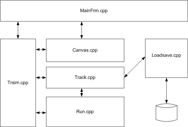
In addition to the main modules shown in the diagram there are many other modules that manage additional features such as itineraries and the various dialog windows.
The following diagram shows the main data structure of the program and their relationships:
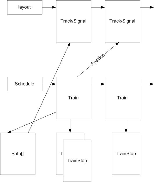
Data Structure Description
- class Track
The Track structure describes a track element placed on the layout. The same Track structure is used not only for actual tracks, but also for signals, switches, icons and all other elements that the author can place on the layout using the integrated editor.The position of the track element is stored in the x and y fields. These fields are grid coordinates, not physical screen coordinates. The conversion from the grid coordinates to screen coordinates occurs by multiplying the x,y pair times the size of a grid square, that is 9 pixels in normal mode, or 36 pixels in zoom mode.
All elements present on the layout are accessible through the global list layout. There are additional lists that link only tracks, only switches, only signals etc. These lists are used to speed up the look up of a particular element by coordinates or by name.
Many functions in the trsim.cpp file manage these lists (for example findTrack(x, y) or findSignalNamed(name) are typical functions that scan these lists.
The elements of the layout are loaded from and saved to the .trk file by the loadsave.cpp module. - class Train
The Train structure describes the characteristics of each train in the schedule. Each train loaded from the .sch file by the loadsave.cpp module is added to the schedule list, which is sorted by entry time and shown in the time table view. - class TrainStop
Each train points to a list of TrainStop structures. Each of the TrainStop objects describes one of the stops of the train, mainly recording the name of the station, the arrival and departure times and some additional fields to record delays, late arrivals etc.Trains present on the layout have their position field pointing to the Track element that corresponds to the train's locomotive. This field is changed as the train travels along its path. The paths is recorded in the path array.
There are several other fields that have the train's actual speed, its maximum speed and the last speed limit seen by the train, plus the next speed limit (if known) found in the path and the next stop point in the path (if known). These two last fields are used to compute the acceleration and deceleration of the train.
Code Organization
run.cpp
The main module is run.cpp. The code in this module controls train movements according to the ticking of the simulated clock. The function time_step() simulates 1 second by scanning the schedule list and changing their state based on different conditions. Trains can be in one of the following states:
- train_READY
The train has never entered in the layout. For every simulated second the program checks if the entry time is before the current simulated time, and if so, the program looks for the entry point of the train in the layout and if there is a clear path from the entry point to the next signal or exit point. If all checks are okay, the train state is changed to train_RUNNING. - train_RUNNING
The train is running in some point in the layout. For every second of simulated time the function run_train() is called. This function computes the speed and advances the train along its path. The path of each train is delimited by the next signal. When the train has reached the signal at the end of the current path, the program checks the aspect of the signal, and if it is not red, the path after the signal is computed and the train moves beyond the signal. If the signal is red, the train's state changes to train_WAITING. If the train has reached a station where it has a stop, the train's state changes to train_STOPPED; in the case where the station's is the final destination of the train, the state is changed to train_ARRIVED. Finally, if the end of the current path is an entry/exit point, and if the train has no tail, the train's state is changed to train_ARRIVED. - train_STOPPED
A train stopped at a station has the train_STOPPED state. For every second of simulated time the program checks if the estimated time of departure is less than the current simulated time, and if so, the state of the train is set to train_RUNNING. - train_WAITING
A train stopped at a signal has the train_WAITING state. For every second of simulated time the program checks the aspect of the signal. If the signal is still red, the program increases the penalties count. If the signal is not red anymore, the state of the train is changed to train_RUNNING. - train_ARRIVED
A train that has completely exited the layout, or that has arrived to a station that is the train's final destination has the train_ARRIVED state. Only the rolling stock of trains in this state can be assigned to other trains.
A running train follows a path that is determined the first
time that the train enters the block delimited by 2 signals
or by a signal and an entry/exit point.
This path is modified by the user by throwing the switches
before clearing the controlling signal. When a signal is
cleared, the program checks that the controlled path is
not locked (for example because there is another train
or because there is an intersecting path that is already blocked,
or because a switch is not in the correct position.)
If the block is not locked, the program clears each track element
with green (or white if the train is shunting), effectively
locking the path to the signal.
This computation is performed by the function findPath0().
When a train reaches the signal, and the signal is not red, the train enters the block and the list of track elements beyond the signal is added to the train's path[] array. As the train travels along each track element, the elements are removed from the path[] array and colored black, thus making them available for selection by another path.
Moreover, every time the train crosses a signal, the program computes the length in meters of the path from the train's position to the next stop point (for example a station where the train has a stop or the next signal, if red). Similarly, the program computes the distance to the next speed limit. These 2 distances are used to compute the deceleration curve when the train approaches a speed reduction or a stop. They are also recomputed every time a train departs from a station or when the train crosses a train with a speed limit indication.
track.cpp
The track.cpp module has code that draws the various
layout elements according to their type (track, switch, signal, etc.)
and their state (free, blocked, thrown, signal aspect etc.).
Whereas the run.cpp module handles the dynamic
aspect of the simulation, the track.cpp handles
the static aspect, managing the relations among the various
layout elements.
Of particular interest in this module are the track_walkeast/west() and swtch_walkeast/west. These functions compute the next track element or switch that can be reached from a given element along a given direction.
By repeatedly calling one of these 4 functions, the function findPath0() can compute the path a train will travel when in enters a block.
trainsim.cpp
The trainsim.cpp module has a number of functions and can be considered the general manager of the system. This module calls many functions, according to the operation that the program must execute.
Since the beginning I decided that all the operations would be described by string commands. These commands are then parsed by the trainsim_cmd() function and the corresponding function called to perform the command.
This decision was very beneficial, since it allowed
adding advanced features without having to rewrite a lot
of code. Some of these features are: the addition of
triggers with associated actions, the execution of
commands from the scripts, the possible record and replay
of a simualtion (not currently active) and the communication
with other programs through a
loadsave.cpp
This module handles the saving of a layout in the .trk file, and the loading of a layout from the .trk, .sch and .pth files. It also creates the various reports in HTML format.
Here as well I decided to use plain text for all files. This decision has the advantage of allowing the writing of auxilliary programs to manipulate the data, such as the TASPO program by Paolo Rosati to cut-paste of layout regions.
The .trk file has a rather cryptic format, since I expected it to be read and written only by Traindir. This has not made life easy for the people who wanted to manipulate it.
The .sch and .pth files are in a more humanly readable foramt, since it was decided from the beginning that they should be created manually by the user with an external text editor. Their structure is described in the on-line User's Manual.
Canvas.cpp and MainFrm.cpp
These modules handle the user interface. The Canvas.cpp module handles the drawing of the on-screen bit map, by converting the elements in the layout list and the train present on the layout into images.
Moreover it handles UI events from the user, such as mouse clicks, and the coordinate conversion.
The MainFrm.cpp module handles the aggregation of the various views in a window frame, managing views resizing, scrolling, menu and toolbar selection etc.
tdscript.cpp
This module has most of the script interpreter code. In it there are functions to read a script from a number of sources, such as the schedule file or the layout file. When a script is read, it is converted into an internal data structure. The various functions (events handlers such as OnCleared: and OnUpdate: are isolated and saved in fields associated with the correspoinding track element or train.
The statements for each event handler are parsed by the ParseStatement() into an Abstract Syntax Tree (AST). This allows a quick interpretation of the conditional blocks and their nesting.
The InterpreterData::Execute() function is called every time that there is an event and there is a script associated to the event for the track element or train, such as when the user clicks on a signal and the signal has an associated script. The function traverses the AST and decides for each statement which operation should be performed. For if statements, the function InterpreterData::Evaluate() is called to check if the condition is met, and to decide whether to continue execution of the "true" branch or of the "false" branch.
This page is maintained by g_caprino@gmail.com
(Remove the _ before sending the message.)
Created on: October 24, 2010