 English -
The editor
Once the user has experienced how difficult it is to manage a line or a station
when there is intense traffic, it is possible to start experimenting with the
editor, both to modify one of the existing layouts (for example adding a
platform to allow more trains to arrive on time), and to create your own
layout.
Clicking on the "Edit+Edit" menu, the tool bar is shown in place of the general schedule pane. On this tool bar the program lists all possible track elements that can be placed on the layout. The following table shows the different track types:
  |
Horizontal tracks |   |
Vertical tracks |
 |
Crossing tracks |  |
Diagonal tracks |
  |
Horizontal switches |  |
Vertical switches |
  |
Protection signals |   |
Automatic block signals |
The button  is used to
remove a line element from the layout.
is used to
remove a line element from the layout.
The button  represent a platform or a station's building. It is used only as a decoration,
since it doesn't affect the train's behavior.
represent a platform or a station's building. It is used only as a decoration,
since it doesn't affect the train's behavior.
The button with the camera  is used to specify a user-created icon. These icons are contained
in a file with the .xpm extension. To specify the file name, place the
camera on the layout, then open the track properties dialog, by clicking with
the right button on the camera, and enter the name of the file in the "Station"
field. To create an .xpm file, one can use any graphic editing program,
such as the excellent and free Greenfish Icon Editor Pro, with which one can also convert icons from the .bmp format
to the .xpm format, and viceversa.
is used to specify a user-created icon. These icons are contained
in a file with the .xpm extension. To specify the file name, place the
camera on the layout, then open the track properties dialog, by clicking with
the right button on the camera, and enter the name of the file in the "Station"
field. To create an .xpm file, one can use any graphic editing program,
such as the excellent and free Greenfish Icon Editor Pro, with which one can also convert icons from the .bmp format
to the .xpm format, and viceversa.
The buttons  are used to place descriptions. To change the text of a description after having
put it on the layout, click on the text with the right button and change the
text in the dialog.
are used to place descriptions. To change the text of a description after having
put it on the layout, click on the text with the right button and change the
text in the dialog.
The button  is used to
specify the motive power for all track elements that will be placed on the layout from
now on. Track elements already on the layout are not affected. In this way one can
deine a sequence of track elements where electric trains can travel. If no value is
specified, and one or more trains specify their motive power in the schedule file,
then the program will let only trains with diesel or steam motive power to travel
on the track element. See the schedule file creation for more details.
is used to
specify the motive power for all track elements that will be placed on the layout from
now on. Track elements already on the layout are not affected. In this way one can
deine a sequence of track elements where electric trains can travel. If no value is
specified, and one or more trains specify their motive power in the schedule file,
then the program will let only trains with diesel or steam motive power to travel
on the track element. See the schedule file creation for more details.
The "Link..." and "...to..." buttons require a more detailed
description. These tools are used to link different points of the layout. First
you have to select the  tool, then click on the first object to be linked;
this automatically selects the
tool, then click on the first object to be linked;
this automatically selects the  tool; then click on the second object to be linked; the "Link..."
tool will be selected again to show that the link has been properly set up.
tool; then click on the second object to be linked; the "Link..."
tool will be selected again to show that the link has been properly set up.
More precisely:
- It is possible to link two switches so that, when simulating, clicking on a switch will automatically throw the linked switch.
- It is also possible to link two terminal points of a line, so that a train that would exit the layout from the first point will re-enter the layout from the second point. This trick is used to break a long line.
- Each signal placed on the layout must be linked to the track protected by that signal.
- It is necessary to define every point of entry or exit from the layout with some text. This text can be a letter, number or a word. After you placed the text with the "Abc..." tool, you must link the text with the track by using the "Link...to..." tools, so that that track becomes an entry/exit point.
To speed up the creation of many layouts, it is possible to create your own
standard elements and place them several times on the layout being created.
These macros are simply mini-layouts that are created with the
same editor and saved on disk in the same way as used for normal layouts.
Obviously, there will not be any schedule file associated with a macro file.
To use a macro, one must first select the desired macro by clicking on  .
Traindir will ask the name of the file containing the macro. Once specified the
file name, the program will automatically select the
.
Traindir will ask the name of the file containing the macro. Once specified the
file name, the program will automatically select the  button, to tell the user that he has to place the selected macro at the desired
position on the layout. From now on, until the user selects a new tool, every
time one clicks on the layout, the selected macro will be placed on the layout,
including all the additional elements like signals, platforms, links etc.
button, to tell the user that he has to place the selected macro at the desired
position on the layout. From now on, until the user selects a new tool, every
time one clicks on the layout, the selected macro will be placed on the layout,
including all the additional elements like signals, platforms, links etc.
A typical macro is used in the construction of several sections in a
2-tracks line, or of a number of stations with sidings on a 1-track line.
To create your own macro, just start with an empty layout, and place the
track elements as if you were building a real layout. The only requirement is
that you must place the elements as close as possible to the upper-left corner
(e.g. at the 0,0 coordinate). As an excercise, try to modify the 2 macros
provided with the program, called "2tracks" and "southst".
The  button is used to
place on the layout a button to select an itinerary. After you've placed the
button on the layout, right-click on the button's icon, and enter the name of
the itinerary. For the creation of an itinerary, see the specific
chapter.
button is used to
place on the layout a button to select an itinerary. After you've placed the
button on the layout, right-click on the button's icon, and enter the name of
the itinerary. For the creation of an itinerary, see the specific
chapter.
The  buttons are
used to move rectangular areas of the layout to a new position. They work as
follows:
buttons are
used to move rectangular areas of the layout to a new position. They work as
follows:
- Click on the first button (with the arrow towards the upper left corner) and mark with the mouse the initial coordinate of the rectangle to move;
- The second button (with the arrow towards the lower right corner) is automatically selected. Now mark with the mouse the final coordinate of the rectangle to move;
- The area to move is highlighted on the layout, and the third button (with the two rectangles) is automatically selected. Now click on the new position of the upper-left corner of the rectangle. The program will move all elements (tracks, signals, icons etc.) to the new position, and will recompute all the links to the moved elements.
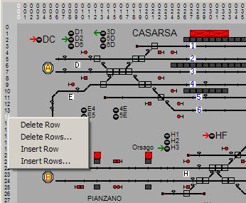
While the coordinates are shown on the layout it is also possible to delete/insert whole rows/columns. To do this, move the mouse on the coordinate of the row (or column) that you want to operate on, and click the right button of the mouse. A pop-up menu simular to the following will appear. Now select the command you want to perform.
After having placed and linked every track element, you must define the lengths and maximum speeds for each line block, so that trains can occupy that line block for an appropriate amount of time. To do this, click with the right mouse button on each line element where you want to define a length and/or a speed limit. A dialog will popup with the current properties of that track element. Just modify or enter new values for the properties.
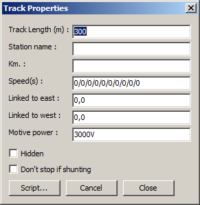
If you enter a text in the "Station" field, that track element will be
considered a station where trains can stop even when the next signal is green,
and where the program will record the arrival and departure times, according to
the train's timetable.
You can enter in the "Speed" field 4 speed limits, according to the train
type. Type 1 trains (see the timetable description) will obey the first speed
limit, type 2 trains will obey the second and so on. If you enter only one
limit, that limit will be obeyed by all trains. Each limit is separated by a
slash from the next. For example, 120/100/80/60.
The fields labeled "Linked to west" and "Linked to east"
show whether that track element has been linked to other track elements by using
the "Link...to..." buttons. Sometimes it is useful to enter the coordinates
manually, or, if one wants to unlink the tracks, one can enter the value "0,0"
in one of the fields.
The field "Motive power" specifies the type of train that can
run on this track element (in the example, 3000V). If a train specifies a corresponding
Power (see the timetable file), then the train can run on this track. If the train
has a different Power, then it will stop at the signal controlling that track element.
A missing Power type for the track or the train indicates steam or diesel power,
and thus no restriction (this is compatible with simulations prior to version 3.8u).
Note that the program doesn't actually have any knowledge of the difference between
different power types (e.g. alternate vs. direct current, or different voltages).
To let a train proceed, the program simply checks that the value specified for
the track exactly matches the value specified for the train.
After the layout has been created, all the entry/exit points have been defined, the signals and switches have been linked, the stations and the lengths and speed limits have been defined, it is possible to save the layout with the command "Edit+Save".
If you change your mind and you want to erase the layout completely and start afresh, use the command "Edit+News".
Signals
A right click on a signal shows the Signals Properties dialog:
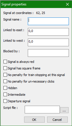
The name of the signal can be changed to make it easier to recognize the signal
when defining itineraries.
"Linked to east" should not be changed.
"Linked to west" indicates the track element that is linked to this
signal. This track element is the first in the block protected by this signal,
and will only be occupied by trains when the signal is not red.
"Blocked by", if specified, restricts this signal to be set to non-red
only when the specified track element is free (that is, it's not occupied and not blocked
by another signal - effectively when the track element is black).
When "Signal is always red" is checked, the signal will always show a red
aspect and it will not be possible to change its aspect. This type of signal is
typically used at the end of spurs.
"Signal has square frame" will cause the frame of the signal to be drawn as a
square as opposed to as a circle. This is typically used for signals that are linked
to the track on the opposite side than normal signals (e.g. if all signals are normally
linked to a track to the right of the signal, a squarish signal should be used if the
linked track is to the left of the signal).
"No penalty for trains stopping at this signal" will not add penalty points
if a train stops at this signal.
"No penalty for un-necessary clicks" will not add penalty points if the signal
is turned from green to red. In fact, the program usually adds one penalty point if the
signal is non-red and the player clicks on it to turn it to red before a train can
cross the signal.
"Hidden" will not cause the signal to be drawn on the layout when in non-edit mode.
The signal can still affect trains according to its aspect. This is typically used with
scripts associated to the signal.
"Intermediate" is used to allow multiple trains traveling in the same direction
to enter a single-track section of a line, and to prevent trains traveling in the opposite
direction from entering the section until all trains have cleared the section.
Intermediate signals behave like automatic signals and are managed by
the program. The user cannot affect their behavior. The "interm.trk" layout included
in the Train Director package shows an example of how intermediate signals are used.
"Departure signal" means this signal is used to let trains depart from a station. As such,
trains will not start moving unless the signal is clear, even if their departure time has
been reached.
"Script file" specifies the name of the file that contains the script
to associate to this signal. See the
scripts page for more information.
Itineraries
An itinerary is a sequence of tracks and switches delimited by two signals. When the itinerary is selected by clicking on the itinerary button which was put on the layout by the author of the scenario, Traindir will try to throw all the switches to the proper position, and then the signal at the start of the itinerary will be set to green. Of course, if there is another train that occupies any of the tracks defined by the itinerary, or if for some reason it is not possible to throw one of the switches, the signal will not be cleared.
To create a new itinerary one must enter in the itinerary editor, by using the
menu "Edit+Itinerary".
The list of the itineraries will be shown in place of the edit tools.
The first step in defining the itinerary is to manually throw all the switches
and to clear the signal at the start of the itinerary. Once Traindir has set the
section to green, one must click with the right mouse button on the start
signal, to show the following dialog:
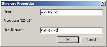
One must then enter the name of the itinerary. This name is completely arbitrary, although it should remind the user of the end-points of the itinerary. The second field in the dialog is used to link several itineraries in a sequence. Every single itinerary is always delimited by 2 signals. However, if one desires to control multiple sections of a line, one can first create the single itineraries, one per section, and then link them by entering in the second field of the dialog above the name of the next itinerary.
The final step in setting an itinerary is to place the activation button on the layout, possibly adding a label to it so that the user will know which itinerary will be activated by clicking on the button. Itinerary buttons are placed on the layout when Traindir is in "Edit+Edit" mode.
Triggers
We recommend not to use the triggers feature. Instead, one should associate scripts to track elements. Using scripts allows much more sophisticated actions to be executed when a train crosses a track element.
In editing mode, if you click on the tool
 the program shows a subset of tools, among which you can see the trigger tools:
 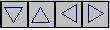 .
Triggers are linked - similarly to signals - to a track element. When a train
(or multiple trains, according to the trigger's properties) crosses the track
element, the trigger may execute a few functions to modify the train's or
layout's state.
.
Triggers are linked - similarly to signals - to a track element. When a train
(or multiple trains, according to the trigger's properties) crosses the track
element, the trigger may execute a few functions to modify the train's or
layout's state.
By right-clicking while in Edit mode on a trigger, you'll see the following
dialog:
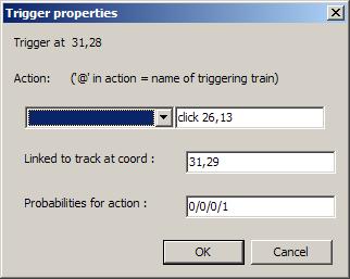
In the drop-menu on the left you can see all possible actions:
- click x,y where 'x,y' are the coordinates of a signal (which will change its state), of a switch (which will be thrown), or of an itinerary button (which will become active);
- rclick x,y where 'x,y' are the coordinates of an object; similar to the above, but simulates a right-click of the mouse on the object. For example, rclick-ing on a green automatic block signal will set the signal to green-green.
- fast is used to increase the time multiplier;
- slow is used to decrease the time multiplier;
- shunt train (e.g. shunt R12345) will start shunting train R12345;
- reverse train (e.g. reverse R12345) will flip train R12345's direction;
- traininfo train (e.g. traininfo R12345) will show train R12345's properties dialog;
- stationinfo station (e.g. stationinfo Piovarolo) will show Piovarolo station's property dialog;
- decelerate speed train (e.g. decelerate 20 R12345) will slow down train R12345 by 20 km/h. This action is canceled the next time the train crosses a speed limit indicator: for example, if the train was running at 60 km/h and it was slowed down to 40 km/h, a subsequent 100 km/h speed limit signal will make the train speed up to 100 km/h (not to 80 km/h).
- accelerate speed train has the effect of speeding up a train, by reversing the effect of a previous "decelerate" command. In any case, it's not possible for the train to run faster than the maximum speed limit for that line section.
One of the boxes in the "Trigger Properties" dialog is the "Probabilities" box. In this box you can enter how likely it will be for each train type to activate the trigger. Note that a "1" probability indicates the lowest probability (i.e. no train will ever activate the trigger), while a "100" value indicates the maximum probability (i.e. all trains will activate the trigger). If you don't enter a probability value, (i.e. the value is all "0"s), the program assumes the maximum probability (100%). For example, entering 1/1/0/0 in this box, will always activate the trigger for all trains of type 3 and 4; it will never activate the trigger for trains of types 1 and 2. This is equivalent to specifying a value of 1/1/100/100.
When a command accepts the name of a train on which the command applies, it's possible to specify the character "@" in place of the name of the train. This character is a substitute for the name of the train that activated the trigger. For example, writing "reverse @" will reverse the direction of all the trains that cross the trigger. This is very useful on terminus stations or to automatically revert the direction of shuttle trains.
It is also possible to specify one or more than one train that will activate the trigger. If you enter the name(s) of the train(s) between the characters "{" and "}", the trigger will be activated (according to the specified probabilities) only by the train(s) listed between the { } characters. For example, entering {ES9876} click x,y the trigger will be activated only by train ES9876. Similarly, the command {ES9876,IC45} click x,y will activate the trigger only when either train ES9876 or train IC45 will cross the trigger.
Finally, it's possible to assign more than one action to a trigger by using the
following notation: click x1,y1; click x2,y2; click x3,y3;reverse R1234
that is by separating the various actions by a semicolon ";". Note however that
it's only possible to specify the list of train between "{" and "}" once, even
when the actions to be performed are more than one. For example, the command
is illegal, because there are two train lists between { }. Only the first list will be considered, because when the program sees {T6,T7} it finds a contradiction, since it will have already executed some of the actions.
The schedule
Each scenario comes with a timetable of all the trains that run on that layout. The timetable is defined in a text file with the same name as the layout but with an extension .sch ("schedule").Unfortunately at the moment it is not possible to enter the timetable from inside the program. Actually, it would be really cumbersome to have to open a dialog for each train and enter by hand the names of the stations and the arrival and departure times.
It is possible to create your own schedule file with any text editor. If one uses Word, one must save the file in MS-DOS text format. Files saved in .doc format will not be recognized by Traindir.
Here's an example of the timetable of two trains that shows the syntax of a .sch file:
# Example from the Alessandria schedule file.
Start: 5:50
Requires: 3.9.1
Type: 3 e646w.xpm e646e.xpm
Power: 3 3000V
Train: R20374
Length: 200
0:00, 5:32, Voghera
5:38, 5:39, Pontecurone
5:46, 5:47, Tortona
5:53, 5:54, S.Giuliano Piemonte
Enter: 5:59, F2
6:00, 6:01, Spinetta
6:07, -, Alessandria
Stock: R20377
When: 167
Notes: Note relative al treno...
.
Train: R20377
Wait: R20374 240
Power: 3000V
Enter: 6:31, Alessandria@1
6:36, 6:37, Spinetta
6:38, -, F1
6:43, 6:44, S.Giuliano Piemonte
6:51, 6:52, Tortona
6:58, 6:59, Pontecurone
7:05, -, Voghera
.
Encoding: Windows-1252
The lines that start with '#' are comments, and are ignored. Empty lines are
also ignored.
Start: tells Train Director to set the clock of the simulation to the
specified time. Normally the simulation would start at 0:00, but if the first
train enters the scenario at 5:50, then there's no point in simulating the time
between 0:00 and 5:50.
Requires: indicates that the simulation was written for a specific version
of Train Director. If the scenario specifies a version higher than the one used,
a warning message is shown in the Events window, but the player can contine to
play, with the understanding that not all functionalities may be operational.
Type: specifies the type of the following trains. Train Director supports
10 train types. Normally type 1 trains are fast trains (IC, ES), type 2 for
mid-range trains, type 3 for regional and commuter trains, and type 4 for
freight or other slow trains. Each train type is identified on the layout by a
different color. It is also possible to specify the name of 2 .xpm files which
contain the definition of the icons to be used for that train type. The first
file specifies the icon of west-bound trains, the second file specifies the icon
of east-bound trains.
Train: defines the beginning of the data for a specific train. It must be
at the start of the line in the file. It is followed by the name of the train.
Length: specifies the length of the train (optional). Trains with a length may
occupy more than one track element when they are running on the layout.
Wait: tells Train Director that the current train cannot enter the layout
before the specified train has arrived to its final destination. This is useful
for shuttle trains, where the same rolling stock is used for multiple trains.
The number after the train name tells how many seconds must pass before Traindir
alerts the user that the train cannot depart because its rolling stock has not
been assigned.
Stock: defines which train will receive the rolling stock of the current
train after the current train arrives at its final destination.
Enter: defines the time and point of entry in the layout. Note that that
point may not be a station. If the train enters from an open-ended track
element, you mush specify a time that will allow the train to arrive at the next
station, which of course will depend by the distance and speed limits between
the open-track line and the station. All the entries preceding the Enter: line
will be ignored.
When there is a dash in place of the departure time of a train it means that
that line defines the final destination of the train. When the train reaches
that point, it will either disappear from the screen, or become availabe to be
assigned to another train or to be shunted to the depot.
A dash in place of the arrival time of a train means that that train will not
stop at that station. Train Director will record the time at which the train
will go through the station, but no penalty will be assigned for late trains.
When:, if present, specifies the days the trains runs on. Use the digit 1
for Monday, 2 for Tuesday, 7 for Sunday.
Speed:, if present, specifies the maximum speed of the train, independently
from the line's speed limit. The train will never travel faster than indicated by
the Speed: entry, even if the line's speed limit is higher.
Notes:, if present, is used to add up to 5 descriptive lines to the
train. The lines will be shown in various placed during the simulation.
Obviously the names of the stations in the schedule file must match the names of the stations defined during the creation of the layout. A @ character after a station name identifies a platform number. If the train arrives at a different platform than the one specified, it will still stop, but the program will add a penalty.
If Power: is present, it specifies the motive power. It can be used
in 2 ways (similar to Type:): outside of any train, it specifies the motive
power of all trains of a certain type (in the example, all type 3 trains have
electric traction at 3000V); inside of a train, it specifies the
motive power of that train only. If Power: is not specified, it is assumed
diesel or steam motive power, and thus the train will be allowed to run
on any type of track.
From version 3.9w it's possible to specify more than one motive power.
This allows simulating trains with multi-voltage locomotives, with more than
one type of locomotive, or bimodal trainsets, suche as Stadler's FLIRT.
The different motive powers must be separated by a comma character. For example:
Power: 3000V,15000VTo specify a bimodal locomotive, use the string "Diesel":
Power: 3000V,DieselIn this case, the train will be able to travel on a 3000V line and also on non-electrified lines. Check the 3.9wmp.trk file in the Examples folder.
Encoding: is optional. If not present, the character encoding of the local
computer is used for the web pages, which is Windows-1252 (Roman characters).
If your scenario uses a different character set, you should add this line
so that people in different countries can display your characters correctly.
This has been tested with Cyrillic characters (Encoding: Windows-1251).
To see how the schedule files look like, just open the schedule file of one of the provided layouts.
How to Specify Late Times
From version 3.7 it is possible to specify random delays for each train. It's possible to specify late entries or late departures for any of the stations where the train is scheduled to stop.
The late times are specified with the '!' character after the entry time or the departure time as in the following example:
Train: T1
Type: 1
Length: 300
	Enter: 0:01!120/10,60/25 A
	0:05, 0:06!120/10,60/20 S
	0:20, -, B
.
In this example the train has a scheduled entry time of 0:01. However 10% of the times it will enter 120 seconds late, or 25% of the times it will enter 60 seconds late. Similarly, the train is scheduled to depart from station S at 0:06; however 10% of the times it will depart 120 seconds late, or 20% of the times it will depart 60 seconds late.
It's possible to specify an unlimited number of delays, even though we recommend to specify the larger delays with the lower probabilities first.
Delta-based Schedules
From Train Director 3.7e, a schedule file can specify arrival and departure times as deltas from the train entrance time or from the train's previous scheduled departure time.
The standard schedule specification requires the author of the scenario to enter all times for all stops. If another train has similar speed (thus it takes the same time to travel from station to station), the author has to enter all times again.
Moreover, the standard specification does not allow to specify a minimum stop time at stations. The default 30 seconds time will be applied at all stops.
The following syntax can now be used to specify arrival and departure times (a sample scenario is available here):
Train: TEST1
Enter: 00:01, A
	00:03, 00:04, B
        +180, +30, C
	+120+90, +60, D
	+180, -, E
.
Here, station B's arrival and departure times are specified with the old syntax, but station C's arrival is computed to be 180 seconds (3 minutes) after the train's departure from station B. Additionally, the departure time from C is computed to be 30 seconds after the scheduled arrival time.
Station D's line is similar: it computes the arrival time to be 120 seconds after the train's departure from station C; in addition, it specifies that the train must stop for at least 90 seconds after its arrival, no matter what the departure time is.
Of course you can also specify a delta time based from the entry time, as in the following example:
Train: TEST2
Enter: 00:20, A
	+120, +60, B
This mechanism can be combined with the specification of a random delay and a minimum stop time after assignment, as in the following example:
Train: TEST4
Wait: TEST3 120
Enter: 00:52!300/50, C
	+120, +60, D
	+120, -, E
.
This train will wait the arrival of TEST3. Then it will compute the departure time using the following logic:
- We start with the base departure time of 00:52;
- If TEST3 arrived after 00:50 (i.e. 120 seconds before our base departure time), we add 120 to TEST3's arrival time, and we use that as the estimated departure time for TEST4;
- A random delay of 300 second is considered with a 50% probability, and applied to the estimated departure time, becoming the effective departure time for TEST4.
Delaying Train Starts
From version 3.8i, it's possible to specify that a train stopped at a red signal will delay its start by a number of seconds after the signal has been cleared. The delay can be specified for all trains of a certain type, or for individual trains.
To specify that a train of a certain type should have a delayed start, use the following notation in the Type: entry:
Type: 1 +20This tells Train Director to wait 20 seconds of simulated time before trains of type 1 cross the signal.
To specify the delayed time for a specific train, use the StartDelay: instruction in the train's schedule, as in:
Train: T4
StartDelay: 30
Enter: 00:30, A
. . .
This specifies that this train only will take 30 seconds to cross the signal after the signal has been cleared.
The "startDelay.trk" simulation in the Train Director package shows how to use this feature.
Specifying Train Acceleration
From version 3.8s, it's possible to specify how quickly a train accelerates to reach
its maximum allowed speed.
The acceleration can be specified for all trains of a certain type, or for individual trains.
If no specific acceleration is specified, Train Director uses an acceleration of 1 km/h per each
simulated second.
To specify that a train of a certain type should use a specific acceleration rate, use the following notation in the Type: entry:
Type: 1 >0.5This tells Train Director to accelerate all type 1 trains by 0.5 km/h per each simulated second.
To specify the acceleration rate for a specific train, use the AccelRate: instruction in the train's schedule, as in:
Train: T4
AccelRate: 2.5
Enter: 00:30, A
. . .
This specifies that this train only will accelerate at a rate of 2.5 km/h per each simulated second.
The "accelRate.trk" simulation in the Train Director package shows how to use this feature.
Unspecified Speeds
When a line section does not specify the speed for a train type, the program uses the speed of type 1 trains (that is the "first" speed specified for the line section).
From version 3.9w, it is possible to tell Train Director to use the speed of the
highest train type (that is the "last" speed specified for the line section).
To do that, add the following line in the .sch file:
DefaultSpeed: last
Thus, if a line section has speed limits 80/100/0/0, and a type 3 train travels on that section, the program will use speed 100. If DefaultSpeed: is not specified, then the program will use speed 80, as in previous versions.
This page is maintained by g_caprino@gmail.com
(remove the _ before sending your message.)
Created on: August 6, 2000